Starter Panel Wiring Diagram
The soft starter is installed between the mains and cable to the motor. It reveals the elements of the circuit as streamlined forms and also the power and also signal connections between the gadgets.
Ford F150 Starter Solenoid Wiring Diagram Database

If you are unsure, please feel free to contact us.

Starter panel wiring diagram. This electrical wiring and connections should be done in. Ryan post navigation 1968 mercury cougar wiring diagram 1991 ford. The main function of car starting circuit is.
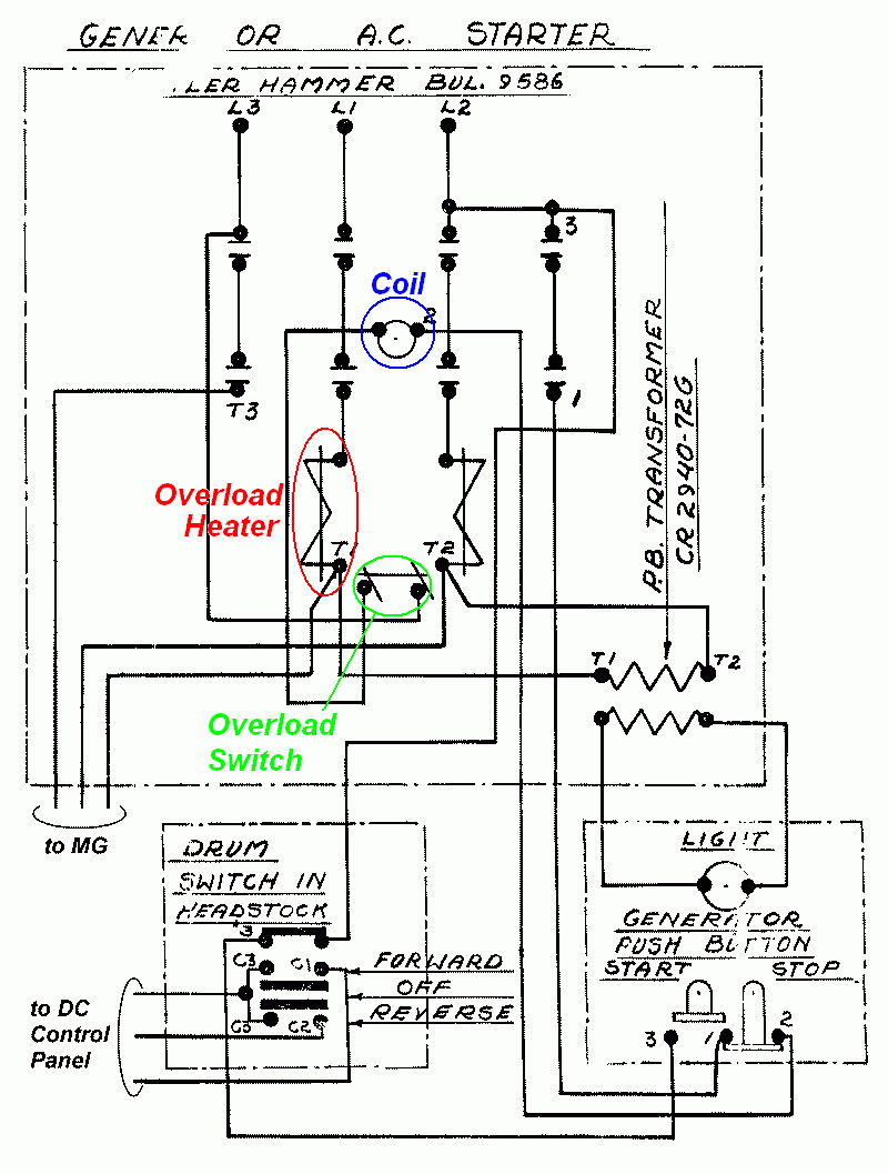
Soft starter main circuit wiring. When you press the on push k1 contactor will hold and k1 no1 become nc. If a mains or isolation contactor is used it is best controlled by the soft starter line relay.
The voltage for the step down transformer is connected between phases l2 and l3. 25122018 25122018 3 comments on 2002 ford f150 starter relay wiring diagram 54l i have a f fx4 supercab l. We are happy to explain further or talk about custom options if you don’t see what you’re looking for.
Dol starter wiring diagram the wiring diagram for a dol stater is shown below. N1 n2 23 if it is the included wiring harness the wires should have their numbers stamped on the jacketing and a sticker should designate the proper screw to mount it to in both the ats and the generator. Wiring diagram book a1 15 b1 b2 16 18 b3 a2 b1 b3 15 supply voltage 16 18 l m h 2 levels b2 l1 f u 1 460 v f u 2 l2 l3 gnd h1 h3 h2 h4 f u 3 x1a f u 4 f u 5 x2a r power on optional x1 x2115 v 230 v h1 h3 h2 h4 optional connection electrostatically shielded transformer f u 6 off on m l1 l2 1 2 stop ol m start 3 start start fiber optic.
The standard connection of an electronic soft starter is 3 wire. K1 no1, pb3, pb4, pb5 should be of potential free contact. It includes directions and diagrams for different types of wiring strategies along with other items like lights, home windows, and so forth.
Shut off the main power. 3 phase distribution board wiring diagram pdf home electrical wiring basic electrical wiring. Each page of this wiring diagram shows the exact wiring for different sections of this control panel.
Wiring diagram consists of several in depth illustrations that show the relationship of varied products. The system controls the motor starter coil m, and uses a spare contact on the starter, m, to seal in the motor starter. Connect or do wiring as per vfd side drawing, you take +24 v from the vfd pcb directly.
Wiring diagrams for the various configurations are below. New honda 13hp wiring starter circuit help. You see that there are four wires that are connected to this switch.
The entry point of the electrical bus comes from the previous page. The specific circuit needs to be respectively learned referring to different typical control circuits. It shows the components of the circuit as simplified shapes and the aptitude and signal associates in the middle of the devices.
These are wires on the back of the emergency stop push button, on the rear of the door. 3 typical car starting system diagram. All the wiring that you see in the panel is done based on the wiring diagram.
I just replaced my broken kaw with a new honda 13ho on my proline toro walk behind. The dol starter comprises an mccb or circuit breaker, contactor and an overload relay for protection. Discussion in 'mechanic and repair' started by messages:
If you have a 120v coil instead of running a line from coil overload l2 you must run coil overload neutral. They show the relative location of the components. An mccb with 4 poles also can be used and the utility neutral then first needs to be connected to the bottom side extreme right.
Smart management module meet the brains that make smart power possible. A direct online starter consists of two buttons, a green button for starting and a red for stopping purpose of the motor. According to previous the lines at a starter relay wiring diagram represents wires.
Terminal markings corresponding to those shown on the diagrams will be found on each switch. With this sort of an illustrative manual, you’ll be capable of troubleshoot, stop, and complete your tasks easily. In the drawing above, we have 4 key elements:
Tion” diagrams, show the actual connection points for the wires to the components and terminals of the controller. An alternative connection is 6 wire or inside delta connection. R , y, b = red, yellow, blue ( 3 phase lines)c.b = general circuit breakermain = mai supplyy = starδ = deltac1, c2, c3 = contatcors (power diagram)o/l = over load relayno = normally opennc = normally closed k1 = contactor (contactor coil) k1/no = contactor.
The wiring diagram is not too much help (see. 460 vac 3 phase 60 hz. They can be used as a guide when wiring the controller.
Generac generator control wiring diagram.joined mar 12 2011 1828 posts. Starter relay wiring diagram you will need an extensive expert and easy to know wiring diagram. Wiring diagram according to new colour code the mccb used here is a 3 pole 60a unit.
Figure 1 is a typical wiring diagram for a three phase magnetic motor starter. Vfd start stop wiring diagram: For instance, for our emergency stop push button, it shows the wiring for this switch.
If we navigate to the first page of our electrical drawings, we can find the specification of the voltage on the bus: An example of a wiring diagram for a motor controller is shown in figure 1. Honda gx electric start wiring diagram ~ i just got a gx engine.
Electrical wiring diagrams of a plc panel. Wiring diagrams do not show the operating mechanism since it is not electrically controlled.
arranque estrella triangulo star delta starter — Postimage

Wiring Diagram For Motor Starter 3 Phase Controller

Dol Starter Panel Wiring Diagram Save Start Stop And Motor
Ahu Starter Panel Wiring Diagram THEINSTRUMENT
Isolation Panel Wiring Diagram
Plc Control Panel Wiring Diagram Pdf

3 Pole Starter Solenoid Wiring Diagram Wiring Diagram
Starter Panel Wiring Diagram 12
3 Phase Electrical Panel Wiring Diagram Chevy Wiring Diagram

Single Phase Motor Wiring Diagram With Capacitor Start Pdf

Direct On Line (DOL) Starter Wiring Diagram EEE COMMUNITY

Yamaha G2 Starter Generator Wiring Diagram Free Picture

Single Phase Submersible Pump Starter Wiring Diagram On

1968 Mustang Starter Wiring Diagram abcdstudio.info

Wiring DOL Starter Motor (Star Delta) Elec Eng World

Capacitor Panel Control Wiring Diagram at Wiring Diagram

Nissan Starter Wiring wiring diagram B88 diesel

Switch Panel Wiring Diagram Complete Wiring Schemas
Submersible Pump Control Box Wiring Diagram For 3 Wire
